My wiring goes like this:
Observatory Cabling
In various forums like Cloudy Nights and Astromart, the question of how to cable your observatory for power and data is often raised. Rather than type the answer again and again, I would like to share what I have learned about wiring an observatory.
My wiring goes like this:
POWER:
I plug a regulated UPS power supply into the wall. From the output of that UPS, I have a six-plug power strip that heads up to the top of the desk to power the laptop. I also have my 12 volt power supply connected to this UPS supply.
My regulated 12 volt, 20 amp power supply is from an old ham radio setup. "Regulated" means it will put out the 12 volt (actually 13 something, if I recall correctly) no matter what the load. It is a very clean power supply from what I hear (little noise). Out of that 12 volt supply, I have a splitter that feeds two 12 volt receptacles on my wall. One is used for my robofocus control box (which I sit near me on the desk). The other 12 volt receptacle on the wall usually goes unused. From the splitter on the 12 volt power supply I also have a ten gauge cable going under the floor and all the way to the mount. It runs in conduit separate from the data cables.
On the mount, the 12 volt cable ends in a splitter, that is hooked to two 12 volt plugs. These plugs are used one for the camera and one for the mount power. I sometimes plug the home-made computer-fan-scope cooler into one of those plugs when the scope/camera itself is not at work.
I also have 110 at the mount, coming straight in from the line power. (Not on UPS, etc. ) I use this for other silly stuff like the fan for the scope cooler sometimes, or a second computer/camera if I am running two setups that night, etc.
Powerwise were I to do something different, I would have put at least one more 12 volt plug on my power base at the mount. Otherwise, I am pretty happy with the setup.
DATA and MOUNT CONTROL:
Here I have made some mistakes.
I put the conduit way too deep. As a result, my USB runs were about twenty feet. (in a 10 x 12 observatory). I should have just dropped them under the floor and run them across.
I also thought it would be good to have connectors with a lot of flexibility. I have found out that I would rather have a direct connect rather than connections between various cables. (cable extension cords, and ports and plugs and jacks, etc. ) Let me explain that----I figured I could have a plate at the wall that would connect all the way to a corresponding plate on the mount. The wall and pier plates would contain various corresponding jacks. Then I would hook connector cables from the jacks to the various equipment at the pier side and to the computer on the wall side. Reality set in pretty quickly. Actually, most of the equipment was not bothered by the 20 some foot USB cable runs. But.......I had not figured on the messiness of mating all these cables. Mating is always messy it seems. There were gender changers, and once gender changers were attached, the jacks did not fit in the box. And there was corrosion. And there was general flakiness, and things falling out when they should not have been (even though nearly everything was done up with electrician's tape). So, after a year or so of general success, but sometimes frustration, I changed things around to minimize connections.
Another fact of life that I had to deal with is that my guider at the time (an Imaging Source DMK 41) would not play nice with either multi-port USB hubs or extension USB cables. And, to a lesser degree, if I did not do everything just right, I would have devices popping up on the wrong USB ports, and thus need to reconfigure software.
So.....this is what I have now, and it is really trouble free for me.
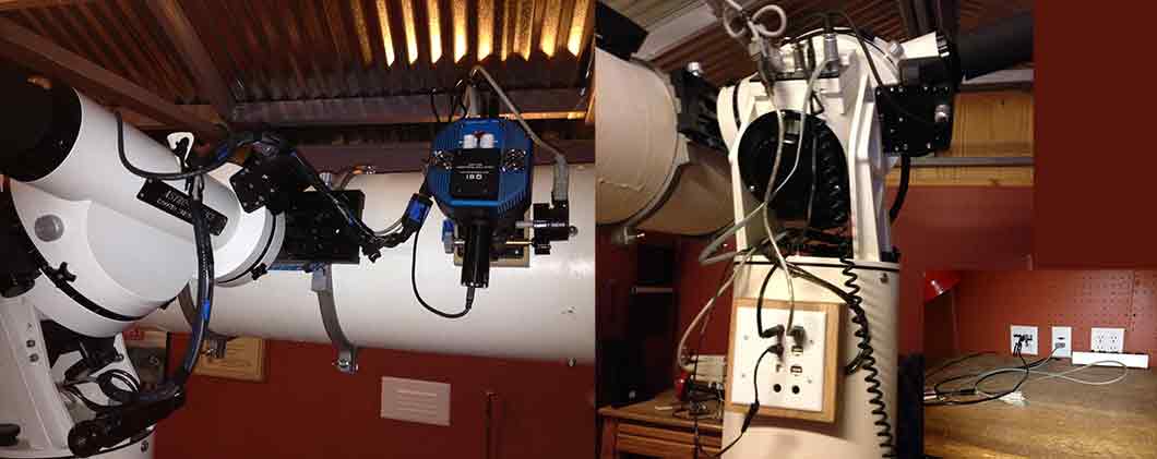
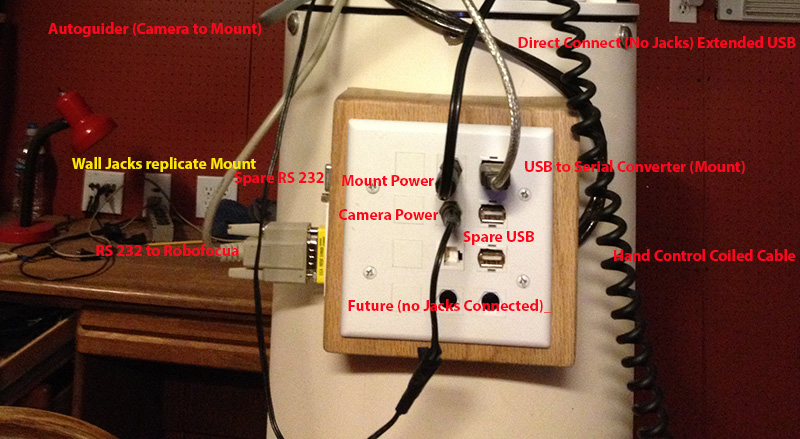
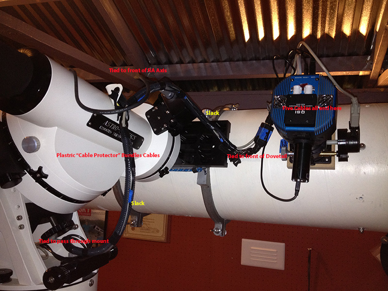
I have USB four ports on my Laptop. Each is occupied by a different device on a typical evening. The Camera and Guider are connected to ports one and two respectively. From port one, a 25 foot cable has about two feet of slack on top of the desk before it disappears into and through the wall, down into a conduit, under ground, into the pier base, up through the concrete of the pier, continuing through the metal pier on top, and out the side of the "jack" box. From there, in a continuous run, this same cable comes up through the mount, with a little slack attaches to the RA axis, and with a little more slack to the Dovetail just above the Dec Axis, and a little bit further to about six inches away from the camera. Another cable comes from port two on the computer and parallels the first (same conduit) to the same position. A very short USB cable then connects the camera and guider respectively to these ports. So--with that little six incher, and the 25 footer, I now have only two pieces of wire (three connections altogether where I once had something like 11 counting the gender changers) on each of those runs. I really do not know what the magic of that 25 foot cable is. It is obviously an "extender." but there is no electronics fifteen feet down to let it get the extra distance. Other extender cables I had had to have a bundle of electronics every fifteen feet!
Coming out of port three, I have a USB-Serial connector that runs the Robofocus. From the Robofocus, I have a DB9 connector that heads back to the wall. (see more on RS232 serials later).
Out of the laptop's port four, I have a short cable that connects to the wall and runs in one of the USB cables that I originally installed over to the mount, through the various extenders, gender changers, etc. I plug a USB-serial connector into the jack and that goes to the mount.
I still have three other USB connectors on the original jack setup. They are live if I choose to use them. However, I find I prefer that one-shot cable to the multiple extenders and such that are in those connections.
I also have two RS232 lines running from the wall to the mount. These have been very reliable. They were, however, rather hard to set up. The cable ends would not fit through the conduit. To solve this problem, I cut the wire, pulled the cable, and then re-soldered the nine wires, re-wrapped them in insulation, and so forth. I was surprised when it worked.....but it has been happy ever since. These have jacks on the wall section, and then run through the wall, through conduit under ground, to the pier, and out the junction box. I use one for the Robofocus, and the other is unused. I could move the mount's USB-Serial converter to the desk area, and send the output through this second RS-232 serial line, but I actually have less excess cable clutter using the USB line for the long run (as described earlier).
OTHER CABLES:
When running cable, I pulled some CAT-6 and some six conductor RJ-something (like used in ST-4 autoguider cable), but have not found a need to connect these cables to their prospective jacks.
If I were to purchase a rotator, I would probably be able to run it through one of the existing USB cables.
One cable has not been mentioned yet. This is a standard autoguider cable that runs from the imaging camera, down the same route as the other cables, to the autoguider port on the mount itself. It never gets to the pier.
MINIMIZING CLUTTER AND SNAGS:
I have found through the years that it is quite possible to minimize the possibility of snags by bundling cables and thinking out the route they take.
Bundling means making many cords into one. On my setup I have five cords all starting at the same place. The ports for the Robofocus motor (1 cable), for the autoguider data and power (1), and for the imaging camera (3 total) are all within five inches of each other. I need a little flexibility at the end (so the focuser can run in and out, etc.) but otherwise, I can treat them all as one cable. So, about eight inches from their terminus, they are gathered together and encased in a plastic wrap. There are various kinds available, including harder plastic cable protectors, spiral wrap, cable ties, and even in its simplest form, a wrapping of electrical tape. They run bundled together like this until it is time for them to split off at their various jacks.
The Route question can seem complicated because of two seemingly conflicting needs:
...... You need enough slack that the cable never restricts the movement of the mount.
and
....... Every bit of slack is another place for something to snag.
The solution is simplified once you realize that you need slack only where there is movement. And in a German Equatorial Mount there are only two places for movement, the RA axis and the DEC axis. (Okay, you need a little flexibility on the focuser, perhaps, and if you had a rotator----but you get the point.) So, get rid of all slack everywhere except those two places. Tie your cable bundle to a place on the tube or dovetail. Run it back to just above the Dec Axis. Then let it jump loosely (just enough slack to let it go as far as it ever goes in dec, and no more) to the center of the RA axis. From there, give it enough slack that it can go from one extreme of RA motion to the other, but no more. And tie it down again. You have to figure out where those places are on your mount, but on mine the slack runs from the front of the dovetail to the fitting that normally covers the Polar Alignment Scope. (In a permanent installation, I never use the polar alignment scope. So, I made a small bracket to hold the cables. ) Check it out, rotating your scope from one extreme to another, and make sure you have enough slack. But tighten up anything you do not need.
OTHER NOTES:
Just about everything you will be plugging and unplugging in the way of data and communication can be facilitated with Keystone jacks. Google them up. You will find, USB, 12 volt power, Cat 5/6, and so forth. These clean wall plates, with their various customizing attachments, make for nice installations.
Behind the desk in my observatory, I have a 2 foot by 16 inches (distance between studs) cutout in the wall that I can remove to provide me access to all the conduits I have running from that corner of the observatory to the pier. It is pegboard, just like the rest of my walls. This allows me easy access if I want to change something.
When I originally pulled cables I pulled several through the same conduit at the same time. I also pulled extra pulling twine through at the same time. This allows me to pull even more cable in if I need it. But pull gently. Pulling cable through a conduit that already has cable can be tricky----but it is not as hard as I imagined it would be. It is worth a try if you have a good fishing line, or an already pulled piece of pulling twine. IF, however, it does not work, the alternative of pulling all the old cable out, and pulling it back through again is also not as difficult as it sounds.
Conduit is cheap. Tearing up a floor, or digging the trench is not. Put in a few extra conduits, and oversize it. It really is cheap.
Corrosion, loose fitting, and all that really screw things up. Minimize the number of connections you have to make whenever possible.